Module 5: VPC Peering Assignment
Problem Statement: Working for an organization, you are required to provide them a safe and secure environment for the deployment of their resources. They might require different types of connectivity. Implement the following to fulfill the requirements of the company.
Tasks To Be Performed:
- Create 2 VPCs in the North Virginia region named
MYVPC1andMYVPC2- Create one VPC in the Oregon region named
VPCOregon1- Create a peering connection between
MYVPC1andMYVPC2- Create a peering connection between
MYVPC2andVPCOregon1
Step 1: Create the VPCs
- I’ll log in to the AWS Management Console:
- I’ll open my web browser.
- I’ll navigate to the AWS Management Console and sign in.
- Next, I’ll navigate to the VPC Dashboard:
- In the AWS Services search bar, I’ll type “VPC” and select the “VPC” service.
- I’ll then create
MYVPC1in North Virginia:
- I’ll make sure my region is set to North Virginia (us-east-1).
- On the VPC Dashboard, I’ll click on “Your VPCs”.
- I’ll click “Create VPC”.
- I’ll name it
MYVPC1and set the CIDR block as10.0.1.0/24. - I’ll click “Create”.
- Now, I’ll create
MYVPC2in North Virginia:
- I’ll follow the same process, naming it
MYVPC2with the CIDR block10.0.2.0/24.
- I’ll switch to the Oregon region to create
VPCOregon1:
- I’ll change my region to Oregon (us-west-2) at the top right corner of the AWS console.
- Again, I’ll follow the VPC creation process, naming it
VPCOregon1with the CIDR block10.0.3.0/24.
Step 2: Set up VPC Peering Connections
- I’ll set up peering between
MYVPC1andMYVPC2:
- I’ll make sure my region is still set to North Virginia (us-east-1).
- On the VPC Dashboard, I’ll go to “Peering connections”.
- I’ll click ” Create peering connection”.
- I’ll name the connection
Peering-MYVPC1-MYVPC2. - For “Requester VPC”, I’ll choose
MYVPC1. - For “Accepter VPC”, I’ll choose
MYVPC2.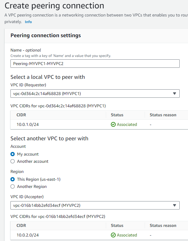
- I’ll click “Create peering connection”.
- After creating, I’ll select the new peering connection, click “Actions”, and choose “Accept Request”.
- Next, I’ll set up peering between
MYVPC2andVPCOregon1:
- Staying in North Virginia (us-east-1), I’ll go to “Peering Connections”.
- I’ll click “Create Peering Connection”.
- I’ll name it
Peering-MYVPC2-VPCOregon1. - For “Requester VPC”, I’ll choose
MYVPC2. - I’ll change the region for “Accepter” to Oregon (us-west-2) and select
VPCOregon1. - I’ll click ” Create peering connection”.
- Now, I’ll switch my region to Oregon (us-west-2), find my peering connection, click “Actions”, and choose “Accept Request”.


Step 3: Update Route Tables
To ensure the VPCs can communicate, I’ll update their route tables:
- In the VPC Dashboard, I’ll go to “Route tables”.
- I’ll select the route table associated with each VPC.
- Under the “Routes” tab, I’ll click “Edit routes”.
- I’ll add new routes:
- For
MYVPC1, I’ll point toMYVPC2’s CIDR block using the peering connection.- In the “Destination” field, I’ll enter the CIDR block of
MYVPC210.0.2.0/24. - In the “Target” dropdown, I’ll select “Peering Connection” and then select the peering connection between
MYVPC1andMYVPC2from the list.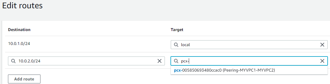
- In the “Destination” field, I’ll enter the CIDR block of
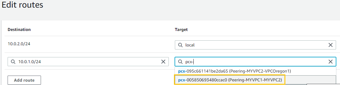
- For
MYVPC2, I’ll point to bothMYVPC1andVPCOregon1’s CIDR blocks using their respective peering connections.MYVPC1:- For “Destination”, I’ll enter the CIDR block of
MYVPC1(10.0.1.0/24). - In “Target”, I’ll select “Peering Connection” and choose the peering connection
VPCOregon1: - For “Destination”, I’ll enter the CIDR block of
VPCOregon1(10.0.3.0/24). - In “Target”, I’ll select “Peering Connection” and choose the peering connection between
MYVPC2andVPCOregon1.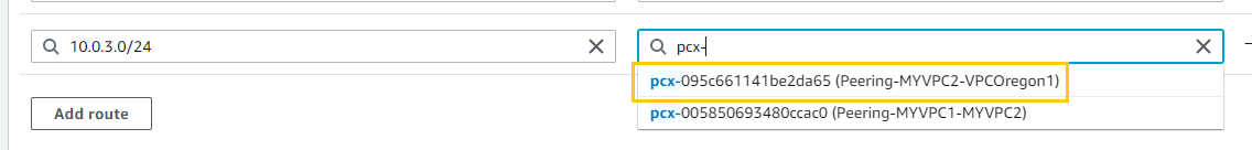
- For “Destination”, I’ll enter the CIDR block of
- For
VPCOregon1, I’ll point toMYVPC2’s CIDR block using the peering connection.- For “Destination”, I’ll enter the CIDR block of
MYVPC210.0.2.0/24. - In “Target”, I’ll select “Peering Connection” and then choose the peering connection between
MYVPC2andVPCOregon1from the list.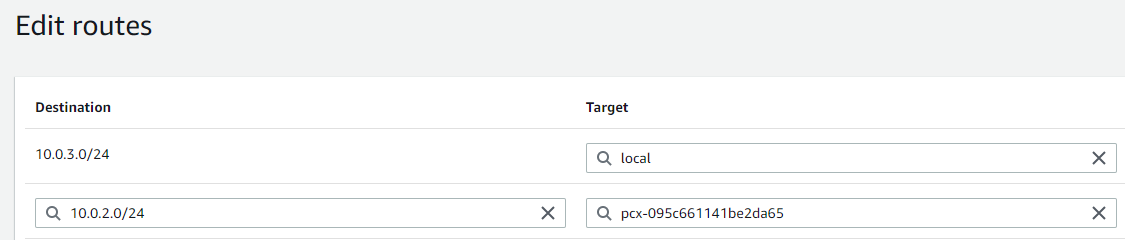
- For “Destination”, I’ll enter the CIDR block of
- I’ll save these routes.
Once I’ve completed these steps, the VPCs should be interconnected as intended.
Connectivity Test Report
Insta1 (10.0.1.153) in
MYVPC1Success
[ec2-user@ip-10-0-1-153 ~]$ ping 10.0.2.37
PING 10.0.2.37 (10.0.2.37) 56(84) bytes of data.
64 bytes from 10.0.2.37: icmp_seq=1 ttl=127 time=4.62 ms
...
Failure
[ec2-user@ip-10-0-1-153 ~]$ ping 10.0.3.59
Not working
Insta2 (10.0.2.37) in
MyVPC2Success
[ec2-user@ip-10-0-2-37 ~]$ ping 10.0.1.153
PING 10.0.1.153 (10.0.1.153) 56(84) bytes of data.
64 bytes from 10.0.1.153: icmp_seq=1 ttl=127 time=1.14 ms
...
Success
[ec2-user@ip-10-0-2-37 ~]$ ping 10.0.3.59
PING 10.0.3.59 (10.0.3.59) 56(84) bytes of data.
64 bytes from 10.0.3.59: icmp_seq=1 ttl=127 time=66.5 ms
...
Insta3 (10.0.3.59) in
VPCOregonFailure
[ec2-user@ip-10-0-3-59 ~]$ ping 10.0.1.153
PING 10.0.1.153 (10.0.1.153) 56(84) bytes of data.
Success
[ec2-user@ip-10-0-3-59 ~]$ ping 10.0.2.37
PING 10.0.2.37 (10.0.2.37) 56(84) bytes of data.
64 bytes from 10.0.2.37: icmp_seq=1 ttl=127 time=65.4 ms
...
Summary
Given AWS’s VPC peering model, the inability of
insta1inMYVPC1to pinginsta3inVPCOregon1was expected. Transitive peering isn’t supported by AWS. Even though there’s a peering connection betweenMYVPC1andMYVPC2, and another one betweenMYVPC2andVPCOregon1, it doesn’t automatically facilitate traffic flow fromMYVPC1directly toVPCOregon1viaMYVPC2.For direct communication between
insta1andinsta3, a peering connection betweenMYVPC1andVPCOregon1is required. This understanding is based on the inherent characteristics of AWS VPC peering. Adjustments to the route tables would follow suit once a direct peering connection is in place.